Discussion Forum - Northstar Chevelle Club

Members Login
Username 
 
Password 
    Remember Me  
Post Info TOPIC: Adding Fusiable Links and Horn Relay hooked up wrong?


2K+ Club

Status: Offline
Posts: 2737
Date:
Adding Fusiable Links and Horn Relay hooked up wrong?
Permalink  


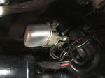
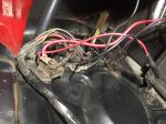
It has come to my attention that gm started using fusible links in 67 to protect the electrical system.  I don't think my 66 has any and it also looks like someone  might have  changed some of the wiring from the horn relay to the fuse block on the radiator support.  My manual shows 4 wires coming off the junction box, I have only 3.  I think it is missing a 12R wire from the junction box to the Horn Relay/  And on the Horn relay there is only 1 wire of each post.  I think there is suppose to be another 12 R at the Horn Relay that goes to the junction box.

Also I think the ammeter gauge is reading backward.  Car has been running this way since I bought it in 2004.

It has also been suggested to add a fusible link in the 10R cable running to the + post on the battery  from the junction box and one on the 10R cable running from the junction box to the horn relay from the junction box.

Whats the best way to clean all this up?   The red wire  from the junction box to the Horn Relay looks to be 10R the same as the wire from junction box the the + on the battery.   With insulation they both measure about 0.160. is the 10R or 12R? Thanks


Attachments
__________________

Jim L

Lake City


Vice President

Status: Offline
Posts: 484
Date:
Permalink  
 

Jim

If the ammeter is reading to the discharge side when the alt is charging, than the ammeter is hooked up backwards, possibly at the firewall or gauge. The gauge just read a portion of the current flow to or from the bat, the measurement is taken from the junction block and the horn relay, the same place that the 10R and the 12R wires are connected which handles most of the current flow. Don't know if the 12R wire is needed in your application, with both 12R and 10R wires connected the ammeter would not be as sensitive to current flow. So maybe the additional 12R wire is only needed for the 61 amp alt?   headscratch  dunno


__________________

Bob W.

Lino Lakes


2K+ Club

Status: Offline
Posts: 2737
Date:
Permalink  
 

Thanks Bob.  Both the 10R and 12R are shown in the wiring diagram for a chevelle both in the AIM and the chassis manual. And they both come from the same post on the junction box to the horn relay.  The chassis manual indicates something different for the passenger car or chevy II regarding  wiring as opposed to a chevelle.

There        is a 14 Black  wire that attaches to the same post as all other wires on radiator support post. That  runs to the fuse panel. There is also a 14 B/DBL/W wire attaching to one of the posts on the horn relay which goes to the fuse panel box, just opposite to the 14 Black wire from the radiator junction box to the fuse panel: just opposite to the other post.  The two post on the  horn relay are connected by a metal buss, so it would seem that which post you use wouldn't  make any difference.

On the  ammeter gauge is a 20 B/DBL/W wire going to the fuse panel which looks like it connects to the 14 B/DBL/W coming from the horn relay.  And a 20B wire going to the fuse panel and looking like it connects to the 14B wire from the junction box.  So I think and thats only a guess, that the wires on the back of the ammeter gauge should be switched.

Do you have any comments on a fusiable link?  Does your 70 use any?


__________________

Jim L

Lake City


Vice President

Status: Offline
Posts: 484
Date:
Permalink  
 

The 10R and if installed, the 12R carry currant to and from the bat (except for cranking). There is a splice that connects the alt, regulator, horn relay, power to the accessories and the 10R wire (which connects to the junction block then to the bat). The regulator controls the system voltage based on the voltage at the splice. During high alt/bat charging there is a voltage drop between the splice and the junction block, it is at these two points where the current flow is measured through the B/DBL/W and 14/20B wires . The voltage drop also protects a discharged bat from the high output of the alt which will extend the life of the bat.

So,,,,,, I don't think the 12R is needed and probably should not be installed.    2cents

Don't know where the best place is to swap the ammeter wiring, on the 70 Chevelle there is a plastic/printed circuit panel that supplies the dash so you cant get it backwards there, my 66 Impala has a counsel gauge gauge panel and is hard wired. Could someone have had the dash apart/out?

As for the fuseable links the 70 has a bat cable with a f/link from the bat to the junction block, there is also two at the splice that protect the ammeter and voltage regulator and one from the horn relay to accessory power. There is also a circuit breaker for the high accessories IE: power windows, power convertible top. The bat cable would be the only F/L that would be easy to install, all other would require main harness removal and rebuild.


__________________

Bob W.

Lino Lakes


2K+ Club

Status: Offline
Posts: 2737
Date:
Permalink  
 

Once again Bob to the rescue.  Checking under the dash, something has changed.  the B and B/DBL/W wires have been spiced and hooked up to a connector that goes into the ammeter gauge.  So most likely hooked up opposite of what it should be.  I just finished reading this article on potential problems with an ammeter and a recommendation to changed to a volt meter.

https://www.americanautowire.com/view-faq/a-word-about-ammeters/

I don't want to change the gauge and think I will be OK as long as I don't have a high output alternator (90-up) and a lots of things that demand power,  Probably will change to a 1966 dated 61 amp alternator would help keep the battery charged. Looks like I should add a fusible link on the 10R wire from the junction box to the battery plus post.  Would putting a fusible link on the 10R wire between the horn relay and junction box protect things from the horn relay down?  Does the fuse in the panel that the 14B wire from the battery protect the ammeter gauge, that article above has me confused?

I am up in the air about the missing 12R wire between the horn relay and the junction box.  I think I might be able to do that this winter by just removing the wires from the junction box and pulling they back through the radiator support so their accessible from the engine compartment.


__________________

Jim L

Lake City


2K+ Club

Status: Offline
Posts: 2737
Date:
Permalink  
 

A little mistake on the wires.  The 10R is missing and the wire to the + battery post is 12R.

Without disassembly of the tap on the wiring harness, it looks like there is a 12R wire from the junction box to the spice ( which runs to the horn relay, regulator, alternator and to the fuse panel.  IS there a way to determine if it is 10R or 12R as it is obvious that one of the wires has been removed.

If I put in the 61 amp alternator does this have to be a 10R wire or I have to add back in the wire so there are 2 wires like in the AIM wiring diagram.


If I add i n a fusible line in between the junction box and the splice does that protect anything assuming I keep the 1 wire set up?


-- Edited by jim larson on Sunday 1st of September 2019 12:03:16 PM

__________________

Jim L

Lake City


2K+ Club

Status: Offline
Posts: 2737
Date:
Permalink  
 

Wondering why in the Impala in 66 they ran a 10R single wire from the junction box to the splice for the horn relay, alternator etc.  But i n the chevelle only they ran 2 wires a 10R and a 12R, does that provide some kind of fusible link?  I believe that used the same 37 and 61 amp alternators, voltage regulators, and horn relays.


-- Edited by jim larson on Sunday 1st of September 2019 12:13:40 PM


-- Edited by jim larson on Sunday 1st of September 2019 12:14:46 PM

__________________

Jim L

Lake City


Vice President

Status: Offline
Posts: 484
Date:
Permalink  
 

jim larson wrote:

A little mistake on the wires.  The 10R is missing and the wire to the + battery post is 12R


 So maybe the 12R is for the 37A alt and the 61A alt requires the 10R wire.

I'm with you on the ammeter, after 50 plus years, other than some one mixing up the gauge connection, it has worked as designed.

I don't agree with much of the article, there has always been a lot of power brought into the cab ether for high amp accessories, starter relays, ignition/acc circuit and old style ammeters that measured directly on the the main power wire which then needs to be run in and out of the cab. My Impala is build this way when the optional council gauge package is ordered.  The more commons ammeter (as in the 66 Chevelle) uses just a small portion of the current to or from the bat to signal the gauge, that wiring could be easily fused to protect the wiring or gauge and probable good to do as a bad connection at ether end of the 12R or 10R wire could also send higher amperage through the gauge and wiring.

Maintenance and inspecting wiring and harnesses is a good thing.  thumbsup

I also don't agree with wiring directly to the bat from the alt, a 3 wire alt regulates output based on the voltage at the splice. The splice is also were the vehicle electrical load is supplied, so when there is high load there will be a voltage drop on the from bat/alt to horn relay/splice, the regulator will then increase the output at the alt to make up for the voltage drop at the splice.        So 14.2 at the splice and higher at the bat.       If the alt is wired to the splice as built, the reg will always try to maintain 14.2 or so regardless of system load, the voltage drop from the splice to bat will diminish as bat charge is replenished and voltage at the bat will never be higher than regulated voltage.

As for fusible link adding one in the 10 or 12R would be redundant if you install a bat cable with a link from bat to junction. Also don't know what is out there foe add on fusible links, I don't like "crimp on" I would use solder only or replace the complete wire. Bad connections heat when amperage is high.

I don't think the extra wire is needed between the relay and junction. As a test you could, after repairing the wiring at the ammeter, than as a run an extra wire from the relay to the bat or j/block and see if it changes the ammeter reading. You ca do this by just turning on electrical loads and comparing amp reading with and without the test wire hooked up, do this without the engine running.


__________________

Bob W.

Lino Lakes


2K+ Club

Status: Offline
Posts: 2737
Date:
Permalink  
 

If I an reading you correctly Bob, these are your recommendations.

Leaving 10R wire from junction post to horn relay as is. Do not add the 12R wire from junction post to battery.

Add fusible link in the 10R wire from junction post to battery + terminal.  Mine is 10R and a reproduction and not 12R as shown in the wiring diagram.

Add a fuse in  which wire, A: from the junction post to the fuse panel or B: from the horn relay to the fuse panel?  To protect the ammeter gauge?


I also have a question regarding  where I get the power for my AC.  My instructions said to run a wire from the solenoid post for the battery up and to a fuse (15 amps) on the firewall and to the underdash power wire.  Is that OK?  In the factory  AC power is sourced from the Horn Relay up to a fuse on the firewall and  then to the AC system.  Is my AC system protected or not?

I got some information last night from American Auto wire that all 66 chevelle V8's with the gauge package got the same Generator FWD wiring harness.  And that was a production part (gm 6289374).  Then the addition 12R which was not in the harness  was added sometimes, But  no one reproduces that wire and it can be added on or not.  Evidently the flint plant that made my car didn't feel it was necessary nor did the KC plant that made the car I disassembled.


-- Edited by jim larson on Tuesday 3rd of September 2019 05:25:00 PM

__________________

Jim L

Lake City


Vice President

Status: Offline
Posts: 484
Date:
Permalink  
 

Sound good

1 wire between the relay and junction block

Add fusible between bat and junction block, you can buy a bat cable with a fusible link.

An inline fuse any where in the gauge circuit would work well, GM installed the fusible link at the junction block. And yes to protect the gauge. If all the current was carried by the gauge circuit due to a bad connection at ether end of the 10R wire the gauge and or wiring would fry.      Ask me how I know!!!         The gauge did not work my car when I bought it.  I became very familiar with this circuit, 12v at both ends and the printed plastic circuit looked as though there was a short the wiring but,      ---- no short----??

Don't know why the instructions said to hook the a/c to the starter, that's full bat power unprotected. Hooked to the bat/starter the voltage drop will increase from the splice/relay to the bat/junction block giving less voltage to the a/c and causing the ammeter read higher than it should. Wired at the horn relay, it is than protected by the fusible bat link, the reg will adjust alt output for the extra load without the voltage drop at the bat and the a/c will see regulated voltage usually 14.2.

Did you do the "test" that I explained in my last post , last paragraph?        Imgonnatsktsk


__________________

Bob W.

Lino Lakes


2K+ Club

Status: Offline
Posts: 2737
Date:
Permalink  
 

Bobs_Place wrote:

Sound good

1 wire between the relay and junction block

Add fusible between bat and junction block, you can buy a bat cable with a fusible link.

An inline fuse any where in the gauge circuit would work well, GM installed the fusible link at the junction block. And yes to protect the gauge. If all the current was carried by the gauge circuit due to a bad connection at ether end of the 10R wire the gauge and or wiring would fry.      Ask me how I know!!!         The gauge did not work my car when I bought it.  I became very familiar with this circuit, 12v at both ends and the printed plastic circuit looked as though there was a short the wiring but,      ---- no short----??

Don't know why the instructions said to hook the a/c to the starter, that's full bat power unprotected. Hooked to the bat/starter the voltage drop will increase from the splice/relay to the bat/junction block giving less voltage to the a/c and causing the ammeter read higher than it should. Wired at the horn relay, it is than protected by the fusible bat link, the reg will adjust alt output for the extra load without the voltage drop at the bat and the a/c will see regulated voltage usually 14.2.

Did you do the "test" that I explained in my last post , last paragraph?        Imgonnatsktsk


 I haven’t done the test yet, I wanted to get it all planed out first.

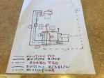
Step 1 is to run AC power from Horn Relay to firewall fuse, thinking 12R.

Step 2 is to install fusible link in 10R wire from junction box to battery + post.

Step 3 is to install inline fuse in ammeter circuit. Should I install one in both the 14B and the 14B/DBL/W  wires?

Step 4 is to install fusible links between splice and regulator (20R), splice and fuse panel (12R),and splice and horn relay (10R).

If ammeter is still reading backwards then switch the wires at the gauge.

Then do the test by adding the 12R wire from junction post to horn relay.

how does this sound or what can I leave out?


I think Karl’s son-in-law has to build a harness from a couple of old harness’s for his El Camino with AC and factory gauges, and might find this post helpful.


-- Edited by jim larson on Wednesday 4th of September 2019 01:02:47 PM

Attachments
__________________

Jim L

Lake City


Vice President

Status: Offline
Posts: 484
Date:
Permalink  
 

1 through 4 look good, but, I would install the test wire as you do step 1 and 2. Don't get fancy with the wire just sneak it under the nuts and tighten them. With the fans and lights on look to see if here is a difference in the ammeter reading with and without the test wire, don't need the engine running.

Not clear on the ammeter, has it always been backwards or is it only when the a/c is on. If it is the a/c don't swap the ammeter wires!!!!!!!

How are you adding in the fusible links, opening up the harness and replacing the complete wire or is there an add on link available that you are installing. If an add on fusible link is what you are using be sure to make good solder connections no crimp on.


__________________

Bob W.

Lino Lakes


1K+ Club

Status: Offline
Posts: 1724
Date:
Permalink  
 

http://www.madelectrical.com/electricaltech/chevymain1.shtml 


Jim this is some good reading for what you are trying to do. This link is also in the tech resources heading on the forum page.


__________________

Chris P
East Central, Mn

66 Chevelle 300 deluxe


Vice President

Status: Offline
Posts: 484
Date:
Permalink  
 

67ss wrote:

http://www.madelectrical.com/electricaltech/chevymain1.shtml 


Jim this is some good reading for what you are trying to do. This link is also in the tech resources heading on the forum page.


 Good article thumbsup


__________________

Bob W.

Lino Lakes


2K+ Club

Status: Offline
Posts: 2737
Date:
Permalink  
 

I read most of the article. Interesting,  I think I understand how the system is suppose to work, just don't quite get where  and what kind of protection is needed.  thanks


__________________

Jim L

Lake City

Page 1 of 1  sorted by
 
Quick Reply

Please log in to post quick replies.

Chatbox
Please log in to join the chat!